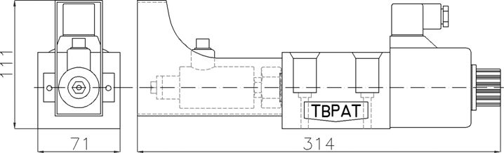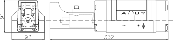

Directional Valve With Linear Variable Differential Transformer (LVDT)
HD-***-G04-P-D-P
Description of Model
|
HD |
*** |
G0* |
DL |
|
Directional Control Valve |
Spool Type |
Valve Size |
Wiring Connection |
|
High Flow Wet Pin Solenoid Directional Control Valve |
Refer List of Spool Function |
G02:1/4"(D03)(NG06) G03:3/8"(D05)(NG10) |
DL: Din type |
|
Solenoid Controlled Pilot Operated Directional Valve |
Refer List of Spool Function |
G04:1/2
DN16 nominal diameter G06:3/4
DN25 nominal diameter |
|
|
B/E/P-D |
P |
AC/DC/RF |
||||||||
|
Series |
Type |
Voltage(V) |
||||||||
|
B: High Efficiency & Low Current Solenoid Directional Control
Valve |
E: Standard High Flow Wet Pin Design Valve |
P: Position |
AC110 |
AC220 |
DC12 |
DC24 |
RF110 |
RF220 |
||
|
Frequency HZ |
||||||||||
|
50 |
60 |
50/60 |
||||||||
|
P:Internal
Pilot *P:External
Pilot |
D:Internal
Drain *D:External
Drain |
|
||||||||
Operation Principle
The safety valves enable accurate spool
positioning by the movement on and off of the magnetic field and the position
sensing point which built into LVDT (Linear Variable Differential Transformer).
The output signals from the sensors and
entering the industrial computer, by this operator data computing to control or
drive hydraulic components and other mechanical structures.
Features
A.
The safety valves get 4 sizes: G02, G03, G04,
G06 suitable for the use of the different flows of hydraulic components.
B.
Protection class reaches IP67, stainless steel
housing is strong with beautiful.
C.
Electronic Specification
|
Input
Supply Voltage |
18~24VCD(±10%) |
|
Recommended Output Current per Channel |
≦50mA |
|
MAX Output
Current per Channel |
400mA |
|
MAX Output Drop |
≦6V |
|
Switch Point Deviation |
≦0.5mmc |
|
Ambient Temperature |
0~50°C |
|
Protection Class |
IP67 |
D.
Statement of Connector and wiring
Initial state switch action status Switch Point A normally closed B normally opened Input Voltage 18-28V (DC) Output 4 2 A B MAX Current 0.4A VCC 1 0V 3

1.
VCC (18~28V, DC), Red wire.
2.
Output B, White wire.
3.
GND, Black wire.
4.
Output A, Blue wire.
5.
The shield wire connected with the junction box.
6.
The switch dedicated to the process of
monitoring.
7.
When the trigger point is reached, output A (4
pin) non-conductive – normally closed.
8.
Output B (2 pin) conductive-normally opened.
9.
The distance of switching operation is due to
the inner tube from the outer tube on the moving position or spool’s thread to
adjust.
Notes
1. When the LVDT (Linear Variable
Differential Transformer) is used in the inductive load, such as the motor, the
relay coil, etc. If the contact point’s contacts open (load circuits) will
produce high induced voltage and the impact (Instantaneous) of the high induced
voltage may damage the LVDT or significantly reduce the safety valve life. For
this reason, recommend that the client use a surge protection device.
2. Don’t re-adjust the safety
valve main body.
Don’t transfer the internal and external components of the safety valve.
Don’t change or transfer the throttle body of the safety valve.
3. The LVDT of the safety valve
can only be set and checked by the manufacturer.
4. The hydraulic system must
ensure that the spools to avoid shock or vibration.
5. Avoid the safety valve fall to
the hard ground from higher than 30㎝.
6. Avoid the pollution of the
hydraulic oils; otherwise, it will reduce the safety valve life even damage.
Filters should use the filtration: âX = 75im, X =
25im class.
7. The hydraulic oils should use
the ISO VG32 or ISO VG45 degree’s hydraulic oils and hydraulic fluid.
View
|
|
|
|
|
|
|
|